Minstrel 4 Jupiter Ace clone build and debug
At the same time as buying the Minstrel 3 I bought a Minstrel 4 which is a Jupiter Ace clone again designed by tynemouth software and was being sold by The future was 8 bit these are now out of stock.
Build notes
Sorry folks I didn’t take any photos during the build process….
This kit comes with less sockets than the Mini PET but the CPU, ROM and RAM are socketed, most of the ICs are HC series CMOS.
The instructions are clearly written and also have a location guide for the components which shows the IC / resistor numbers (there is also one showing the IC types)
The instructions split the computer into sections talking about each circuit section (which is clear and understandable), again no component identification guide so you’ll need to know what a capacitor, diode etc looks like before building it.
Broadly speaking it’s very similar to the Minstrel 3 build but with a video circuit using an ATMega and dual port RAM like the mini PET for video circuitry.
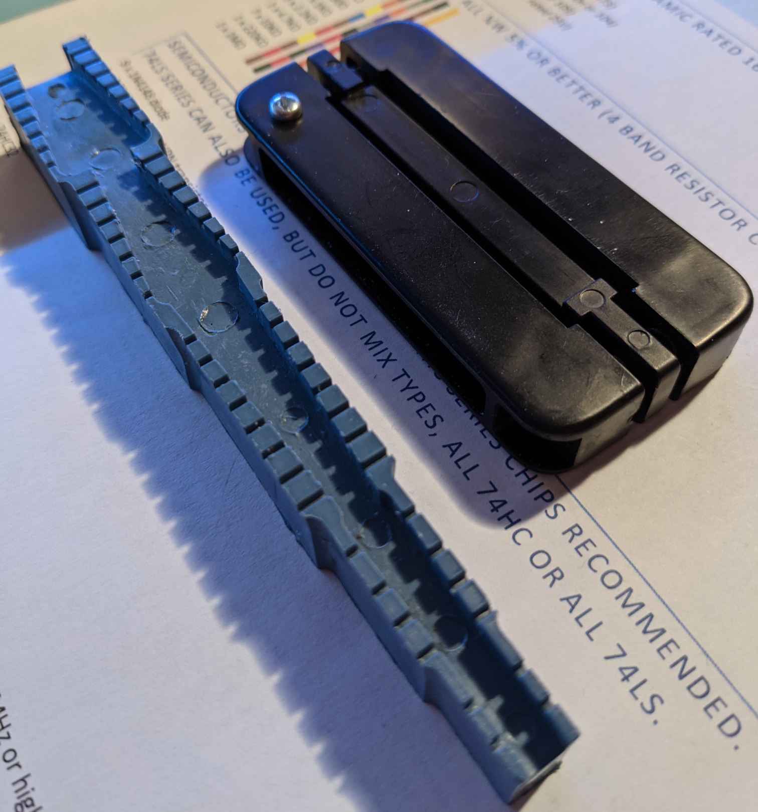
Oh at this point I should include a picture of a tool I bought from Amazon it’s IC Straightener Tool made by Spiratronics.

IC Straightener Tool and a lead bending tool
I’ve shown it in the picture next to a lead bending tool I use for capacitors, diodes and resistors. Basically you can pop a .3” DIP IC in the slot (a .6” slot is on the other side), give a little squeeze and now all the pins are perfect for putting into a board. Saves bending pins on a table and I highly recommend it to those who have to deal with .1” DIP packages.

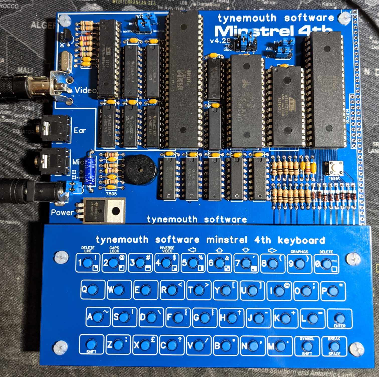
Completed minstrel 4
Once the whole board had been assembled it was time to fire things up.
Debugging the Minstrel 4
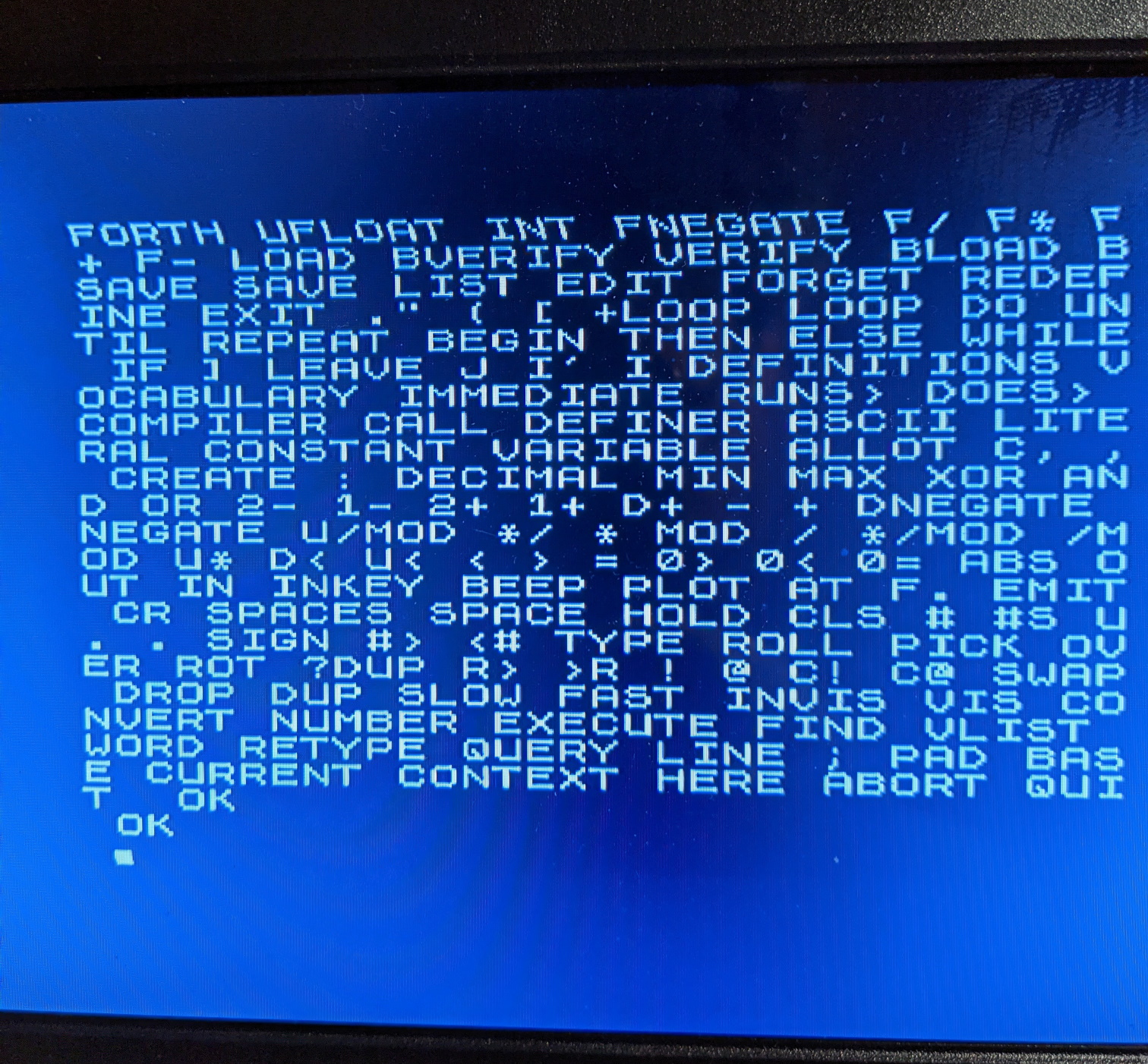
The Minstrel 4 looks like it’s working but the video is a little bit off.

Bad video
At this point I tried to re-flow some of the joints in the video circuit and rechecked all of the components. I got out the little USBee AX logic analyzer and attached it to the Minstrel 4 and had a look at the various digital signals all of which looked okay. I then tried to look at the video signal which the poor USBee couldn’t really deal with as it was outside of it’s 12Mhz sampling range.
I haven’t tried with a different monitor yet but since the analogue(ish) bits of the video circuit are the same as the mini PET and Minstrel 3 I think the cheap LCD monitor I’m using should be fine.
I then did the only thing possible and bought a proper oscilloscope (something I’ve been looking for an excuse to do).

Rigol MSO5104
This particular scope has the bandwidth to debug the Minstrel 4 and I’ve also bought the 16 signal logic analyzer add on which should come in handy. Like most of the Rigol oscilloscopes the firmware can be hacked to expand the scope to a 350Mhz bandwidth and more memory for storage I decided to buy the 100 MHz version which should mean I won’t need to enable the hack for the work I’m planning to do.
It comes with a licence for most of the optional features (SPI / I2C decode, bode plot etc) which seems to be a regular promotion that Rigol run. If you’re happy running the software hack then the current advice from forums seems to be to buy the 70 MHz version with four channels as the cost of the extra two probes covers most of the extra cost.
Note: The current hack patches the binary the scope runs to enable all of the features, each firmware upgrade needs a different patch file and at some point Rigol might start digitally signing everything. Unlike earlier Rigol oscilloscopes you are not generating a fake key.

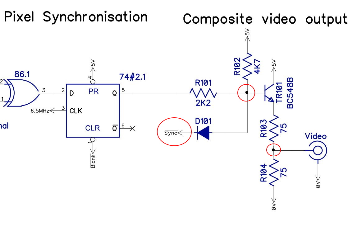
Video Circuit
I shown the output circuit for the Minstrel 4 in the picture above. So the first things I’m going to do is to attach some probes to points I’ve circled to see exactly what the wave forms look like.
Update May 2021 More on this when I actually get around to it (I’ve been short on time due to work and various bits of full size modern PC rebuilding)